|

FLOW SYSTEM FOR FOLLOWING CHEMILUMINESCENT REACTIONS
Background
The reaction of the luminol and the hydrogen peroxide which is catalysed by metal ions is an example of a chemiluminescent reaction. In the chemiluminescent reactions the energy is released in the form of light. The power of emitted radiation is proportional to the hydrogen peroxide concentration; as a consequence the hydrogen peroxide or the concentration of the hydrogen peroxide producing substances can be determined. An example of such reaction is the glucoseoxidase catalysed glucose decomposition. Determining glucose concentration in blood or urine is important for recognising and treating the diabetes, from which more and more people in the developed world suffer.
Task
This activity aims at assembling a flow system for following the chemiluminescent reaction with the SpektraTM spectrometer and finding out the relation between the power of the emitted light and the concentration of the hydrogen peroxide.
Consumables and equipment
For the activity the following items are required:
- SpektraTM spectrometer,
- analytical balance,
- volumetric flask 500 mL,
- volumetric flask 250 mL (2x),
- volumetric flask 200 mL,
- volumetric flask 100 mL (4x),
- glass rod,
- micropipette for volumes 0.05 mL to 2 mL,
- beaker 250 mL,
- beaker 150 mL,
- beaker 25 mL (4x),
- measuring cylinder 10 mL,
- flow-through cell, designed from the Shrinky Dinks Crystal Clear and Shrinky Dinks Brown foils, K & B Innovations, North Lake, USA,
- silicon tubes Clear C-FLEX, O.D. 2.1 mm, I.D. 0.5 mm, Cole-Parmer Instrument Company, Vernon Hills, Illinois, USA,
- filtration flask with rubber stopper (2x),
- tubes of different diameters,
- glass tube with a stopcock,
- glass tube,
- L-shape glass tube,
- water jet pump,
- sodium carbonate,
- sodium hydrogen carbonate,
- ammonium carbonate,
- luminol,
- cobalt(II) chloride hexahydrate,
- hydrogen peroxide (w=30%, ρ=1.1 kg/L).
Hazards

|
Sodium carbonate
R 36
Irritating to eyes.
S 22-26
Do not breathe dust. In case of contact with eyes, rinse immediately with plenty of water and seek medical advice. |
| |
Sodium hydrogen carbonate
/
|
 |
Ammonium carbonate
R 22
Harmful if swallowed. |

|
Luminol
R: 36/37/38
Irritating to eyes, respiratory system and skin.
S: 26-36
In case of contact with eyes, rinse immediately with plenty of water and seek medical advice.
Wear suitable protective clothing.
|

 |
Cobalt(II) chloride hexahydrate
R 49-60-42/43-50/53-68
May cause cancer by inhalation. May impair fertility. May cause sensitization by inhalation and skin contact. Very toxic to aquatic organisms, may cause long-term adverse effects in the aquatic environment. Possible risk of irreversible effects.
S 53-22-36/37-45-61
Avoid exposure - obtain special instructions before use. Do not breathe dust. Wear suitable protective clothing and gloves. In case of accident or if you feel unwell, seek medical advice immediately (show the label where possible). Avoid release to the environment. Refer to special instructions/ Safety data sheets.
|

 |
Hydrogen peroxide
R: 34
Causes burns.
S: 45-36/37/39-3-26
In case of accident or if you feel unwell, seek medical advice immediately (show the label where possible).
Wear suitable protective clothing, gloves and eye/face protection.
Keep in a cool place.
In case of contact with eyes, rinse immediately with plenty of water and seek medical advice. |
Procedures
Preparation of the luminol solution
Into a 250 mL beaker add 125 mL of deionised water, 1 g of Na2CO3 and 0.05 g of luminol and mix until everything dissolves. Than add 6 g of NaHCO3 and 0.125 g of ammonium carbonate and 0.025 g of cobalt chloride hexahydrate. Transfer the solution quantitatively into 250 mL volumetric flask and dilute with deionised water to the mark.
Preparation of the hydrogen peroxide solutions with different concen trations
Prepare solutions with different concentrations by diluting the 30 % hydrogen peroxide solution (r=1.1 kg/L) as indicated in Table 1.
Table 1: Preparation of the solutions with different hydrogen peroxide concentrations
c (mmol/L) |
V (30% H2O2) (mL) |
V (flask) (mL) |
0.971 |
0.05 |
500 |
1.94 |
0.05 |
250 |
2.43 |
0.05 |
200 |
4.85 |
0.05 |
100 |
48.5 |
0.5 |
100 |
97.1 |
1 |
100 |
194 |
2 |
100 |
Designing a flow-through cell
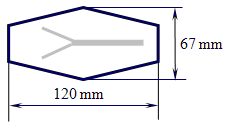
From the Shrinky Dinks crystal clear foil cut two equal hexagonal shapes as indicated in Figure 1. Cut a hexagon of the same shape from the non-transparent brown foil. From the brown hexagon cut out the Y shape channel consisting of a longer 5 mm wide channel and two shorter 2.5 mm wide channels as indicated in Figure 1.

Figure 1: The hexagonal shape cut from the Shrinky Dinks foils with an indicated channel
which is cut out of the non-transparent brown foil.
Sandwich the brown hexagon between the two transparent hexagons. Secure the positions of the hexagons by small quantities of glue close to the final ends of the channel and in the corners. Apply pressure by putting some burden on the top of the hexagon and let the glue dry for 15 minutes. Thermally bond all three layers in an oven at 160 °C. The shape shrinks and thickens. By a 2.1 mm drill bit drill from the side the holes to the ends of the channels and connect the Clear C-FLEX silicon tubes.
Flow system for following luminescent reactions
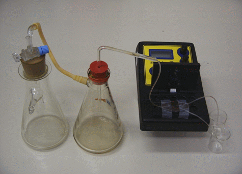
Position the flow-through cell into the measuring chamber so that the channel where the two channels join lies exactly above the sensor of the SpektraTM spectrometer. Fasten the position with the transparent tape. Into the rubber stopper through which two holes are drilled insert a glass tube and a glass tube with a stopcock. Insert the rubber stopper into the first filtration flask and connect the glass tube with no stopcock to the second filtration flask with a rubber tube. Through the second rubber stopper through which a hole is drilled insert the L-shaped glass tube. Connect the glass tube with the silicon tube to the longitudinal channel of the flow-through cell. Insert the silicon tubes coming out of the two other channels into the 25 mL beakers, one of which contains the luminol solution and the other the hydrogen peroxide solution. After the first filtration flask is connected to the water jet pump the reagents are sucked into the channels, they combine and react in the flow resulting in the chemiluminescent reaction which is followed with the SpektraTM spectrometer. The light source of the spectrometer is not in use; the flow-cell is protected from the surrounding light by a box made of the black paper. The electronic amplification SpektraTM spectrometer is set to maximal with the potentiometers in their far right position. The flow system for following the chemiluminescent reaction is presented in Figure 2.

Figure 2: The flow system for following the chemiluminescent reactions with the SpektraTM spectrometer.
Measuring the intensity of the chemiluminescent reaction
Insert the two inlet tubes into two 25 ml beakers filled with deionised water and start sucking water through the system. With the stopcock regulate the suction flow so that it is 2.5 mL/min for an individual beaker. This is more precisely achieved by replacing one of the reservoirs with a measuring cylinder filled with deionised water. Replace the beakers with the beakers filled with the luminol solution and the hydrogen peroxide solution with the lowest concentration and read the measurement. Proceed by repeating the washing the flow system with deionised water and making the measurement for the next hydrogen peroxide concentration until the end. Write the measurements as demonstrated in Table 2.
Results
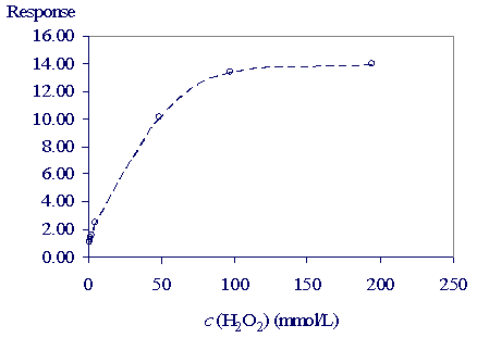
The results are presented in Table 2 and Figure 3.
Table 2: The light intensity of the chemiluminescent reaction for different concentrations
of the hydrogen peroxide
c (mmol/L) |
0.971 |
1.94 |
2.43 |
4.85 |
48.5 |
97.1 |
194 |
Response |
1.1 |
1.4 |
1.6 |
2.5 |
10.1 |
13.4 |
14 |

Figure 3: The light intensity dependence on the hydrogen peroxide concentration.
Discussion
The intensity of light of the chemiluminescent reaction increases with the hydrogen peroxide concentration in the concentration range up to 0.1 mol/L. For low millimolar concentrations of the hydrogen peroxide it can be expected that the relation is linear what is appreciated for determining concentration. With the flow system presented here determining the low concentrations of the hydrogen peroxide is possible.
Developed and prepared by: Dr. Nataša Gros and Karmen Lampreht, University of Ljubljana, Faculty of Chemistry and Chemical Technology, Slovenia. |

